Infinity Mirror или зеркальный тоннель при помощи Arduino.
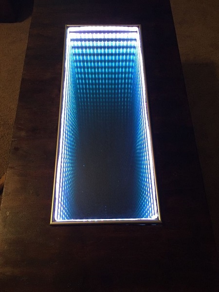
Infinity Mirror дословно переводится как бесконечное зеркало, также этот эффект называют зеркальным тоннелем. Это весьма эффектный прием, который используется для декора различных предметов интерьера или как самостоятельное устройство для декорирования. Сегодня мы преобразим старый стол и сделаем из него настоящее произведение современного искусства. После своего преображения стандартный предмет корпусной мебели не только сможет вписаться в любой интерьер, но и стать его украшением.

Материалы
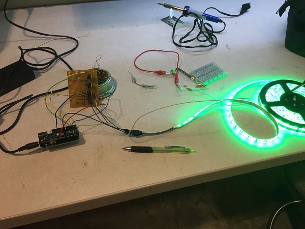
- Плата Arduino Uno;
- Соединительные провода;
- Зеркало;
- Стекло;
- Зеркальная пленка (подойдет автомобильная тонировочная пленка).
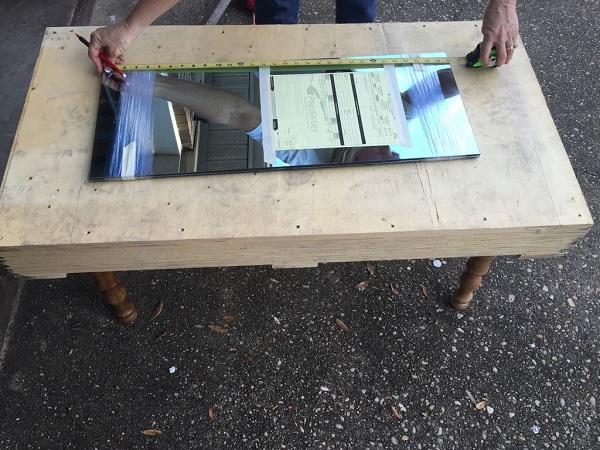
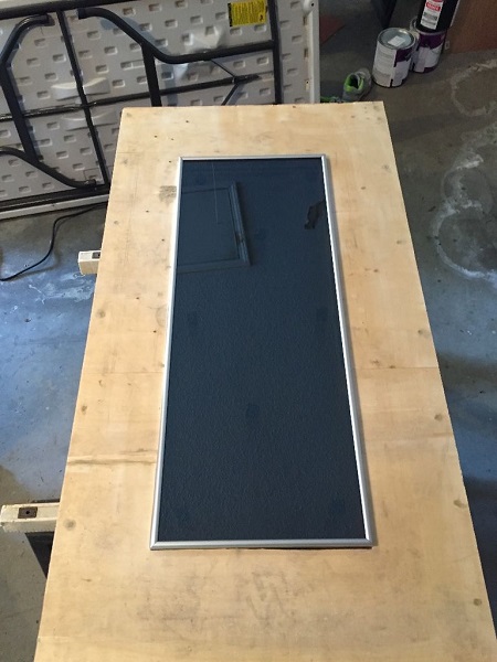
Подготовка стола
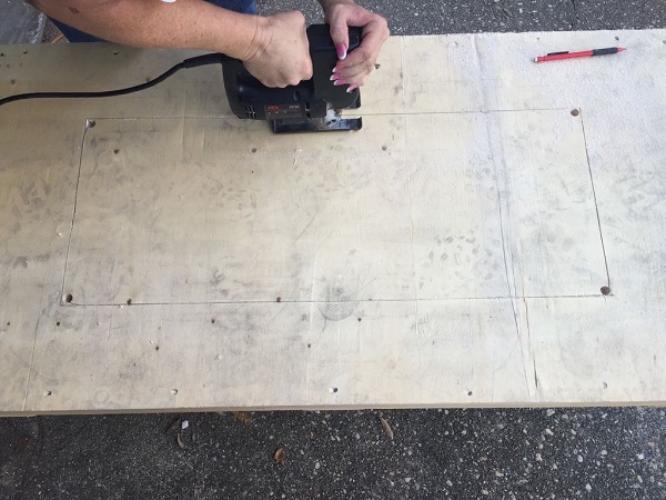
Проще всего положить имеемое зеркало на стол и разметить участок, где именно вы хотите его встроить. Далее следует просверлить 4 отверстия по углам и после этого вырезать всю область лобзиком.
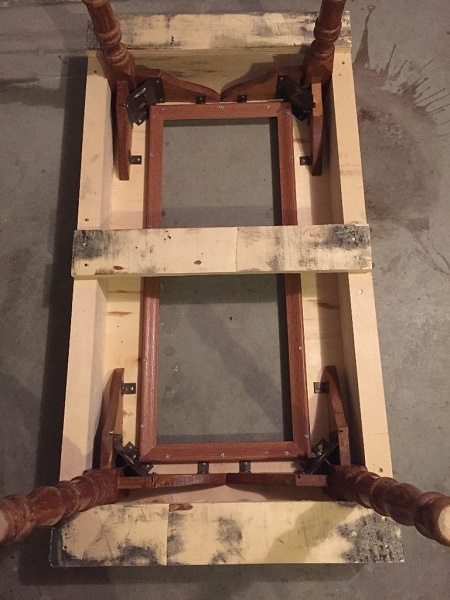
Крепление зеркала
Для крепления зеркала можно использовать рамку, которую следует прикрепить с обратной стороны столешницы. На нее сверху мы и положим зеркальную рамку.
Код
// Pin for the LED
int LEDPin = 13;
int trigger = 0;
int r, g, b;
// Pin to connect to your drawing
int capSensePin = 2;
// This is how high the sensor needs to read in order
// to trigger a touch. You'll find this number
// by trial and error, or you could take readings at
// the start of the program to dynamically calculate this.
int touchedCutoff = 20;
#define REDPIN 5
#define GREENPIN 6
#define BLUEPIN 3
#define FADESPEED 5
void setup() {
Serial.begin(9600);
// Set up the LED
pinMode(LEDPin, OUTPUT);
digitalWrite(LEDPin, LOW);
pinMode(REDPIN, OUTPUT);
pinMode(GREENPIN, OUTPUT);
pinMode(BLUEPIN, OUTPUT);
}
void loop() {
// If the capacitive sensor reads above a certain threshold,
// turn on the LED
if (readCapacitivePin(capSensePin) > touchedCutoff) {
digitalWrite(LEDPin, HIGH);
} else {
digitalWrite(LEDPin, LOW);
}
// Every 500 ms, print the value of the capacitive sensor
if ( (millis() % 500) == 0) {
Serial.print("Capacitive Sensor on Pin 2 reads: ");
Serial.println(readCapacitivePin(capSensePin));
Serial.println(trigger);
}
if (readCapacitivePin(capSensePin) >=250) { //sensitivity
trigger++;
if (trigger >5) {
trigger =0;
}
switch(trigger) { //these are the lighting schemes
case 0:
digitalWrite(REDPIN,255);
digitalWrite(GREENPIN,255);
digitalWrite(BLUEPIN,255);
break;
case 1:
digitalWrite(REDPIN,0);
digitalWrite(GREENPIN,255);
digitalWrite(BLUEPIN,0);
break;
case 2:
digitalWrite(REDPIN,0);
digitalWrite(GREENPIN,255);
digitalWrite(BLUEPIN,255);
break;
case 3:
digitalWrite(REDPIN,255);
digitalWrite(GREENPIN,0);
digitalWrite(BLUEPIN,255);
break;
case 4:
digitalWrite(REDPIN,0);
digitalWrite(GREENPIN,0);
digitalWrite(BLUEPIN,0);
break;
}
}
}
// readCapacitivePin
// Input: Arduino pin number
// Output: A number, from 0 to 17 expressing
// how much capacitance is on the pin
// When you touch the pin, or whatever you have
// attached to it, the number will get higher
// In order for this to work now,
// The pin should have a 1+Megaohm resistor pulling
// it up to +5v.
uint8_t readCapacitivePin(int pinToMeasure) {
// This is how you declare a variable which
// will hold the PORT, PIN, and DDR registers
// on an AVR
volatile uint8_t* port;
volatile uint8_t* ddr;
volatile uint8_t* pin;
// Here we translate the input pin number from
// Arduino pin number to the AVR PORT, PIN, DDR,
// and which bit of those registers we care about.
byte bitmask;
if ((pinToMeasure >= 0) && (pinToMeasure <= 7)) {
port = &PORTD;
ddr = &DDRD;
bitmask = 1 << pinToMeasure;
pin = &PIND;
}
if ((pinToMeasure > 7) && (pinToMeasure <= 13)) {
port = &PORTB;
ddr = &DDRB;
bitmask = 1 << (pinToMeasure - 8);
pin = &PINB;
}
if ((pinToMeasure > 13) && (pinToMeasure <= 19)) {
port = &PORTC;
ddr = &DDRC;
bitmask = 1 << (pinToMeasure - 13);
pin = &PINC;
}
// Discharge the pin first by setting it low and output
*port &= ~(bitmask);
*ddr |= bitmask;
delay(1);
// Make the pin an input WITHOUT the internal pull-up on
*ddr &= ~(bitmask);
// Now see how long the pin to get pulled up
int cycles = 16000;
for(int i = 0; i < cycles; i++) {
if (*pin & bitmask) {
cycles = i;
break;
}
}
// Discharge the pin again by setting it low and output
// It's important to leave the pins low if you want to
// be able to touch more than 1 sensor at a time - if
// the sensor is left pulled high, when you touch
// two sensors, your body will transfer the charge between
// sensors.
*port &= ~(bitmask);
*ddr |= bitmask;
return cycles;
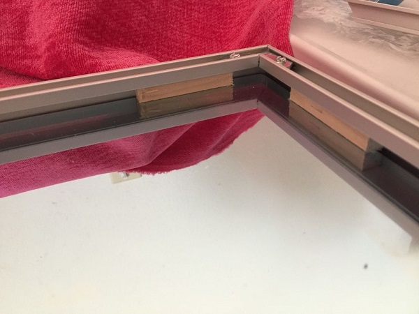
} Обрамление зеркала
Мы использовали алюминиевую рамку для крепления на ней зеркала и стекла.
Первым устанавливается зеркало, затем по периметру клеится светодиодная лента и закрывается все это стеклом с наклеенной на него тонировочной зеркальной пленкой (пленкой вниз).
Установка рамки
Далее необходимо вывести провода от светодиодов и закрепить зеркальную рамку в столешнице.
Остается только подключить рамку к плате и все это к источнику питания.
На этом все, проект полностью готов.
Статья является авторским переводом с сайта instructables.com.
Данная статья является собственностью Amperkot.ru. При перепечатке данного материала активная ссылка на первоисточник, не закрытая для индексации поисковыми системами, обязательна.
Комментарии